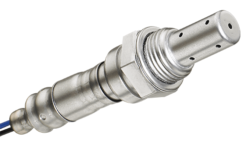
A/F Sensors
Features:
- Tarnish-proof platinum electrodes provides longer life and maintains accuracy
- Quick-response planar zirconia element can quickly detect oxygen concentration
- Measures A/F ratios from approximately 12:1 to 19:1


Increased performance by mapping air/fuel ratios throughout RPM range

Reduces emissions by keeping the
air-fuel mixture at an optimum ratio

Reduces fuel consumption and maximizes catalytic converter life
Mapping Air/Fuel Ratios Throughout RPM Range for Reduced Emissions
DENSO’s air/fuel ratio sensor began to appear in the early 90s as vehicle manufacturers increased demands for better emission standards. DENSO’s air-to-fuel ratio sensor were developed to measure the air-to-fuel ratio information under a wider range of driving conditions. The air/fuel ratio sensor sends information to the engine management computer to makes adjustments based on driving conditions. This wider range and variable adjustments control the motor to burn fuel more efficient and produce less emissions.
As the automotive industry continues to improve on their standards DENSO is keeping the pace with advancements in our engineering to meet the demands from the industry. Also, as light duty fleet owners are holding on to their vehicles for longer periods, DENSO continues to make auto parts available for those critical replacement parts for all applications.
As oxygen sensor technology has evolved, DENSO’s engineers have been there every step of the way. From the first thimble-type sensors to heated, quick-response sensors required to meet ever more stringent emissions regulations, DENSO has supplied the OE industry with quality components. DENSO continues to innovate with the latest development in oxygen sensors, known as air/fuel sensors. These components, also known as wide-band oxygen sensors, have a broader response range to provide much finer control of air/fuel mixtures over a greater variety of operating conditions. DENSO helped to develop this important new technology. Consumers can rely on DENSO First Time Fit® air/fuel sensors.
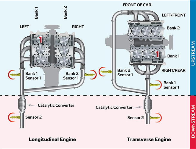
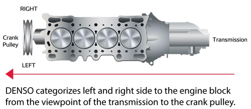
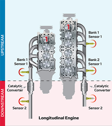
Oxygen and A/F Sensor Positioning: Left or Right?
Many manufacturers’ catalogs identify the left and right side positioning; however, diagnostic tools refer to sensor locations by Bank and Sensor (e.g. Bank 1 Sensor 1).

In the diagrams below, the longitudinal engine orientation illustrations depict rear-wheel drive. In cases of transverse engine (front wheel drive), the concepts are the same, however, the mounting direction is at a 90 degree rotation left or right from longitudinal.
Engine configurations will vary. Please review your service manual or online technical references for accurate engine configurations.
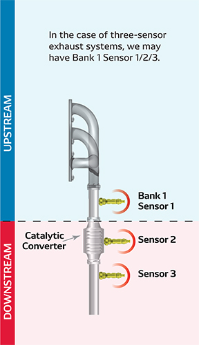
Three-Sensor Exhaust Systems
Inline Single / Split 4/5/6 Cylinder
V6/8/10 Type Dual Exhaust
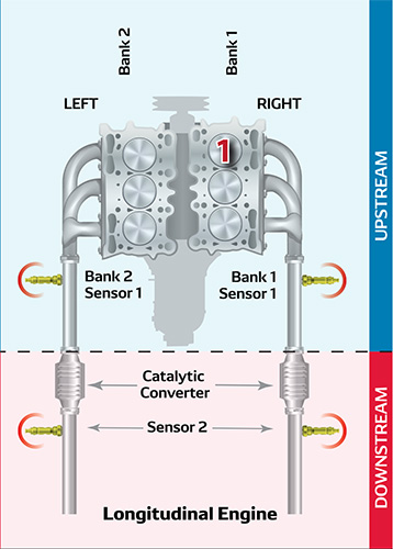
V6/8/10 Type Single Exhaust
