System Diagnosis
Proper vehicle diagnosis requires a plan before you start
Following a set procedure to base your troubleshooting on will help you find the root cause of a problem and prevent unnecessary repeat repairs.
STEP ONE: Understand the Customer’s Concern
- Information collection beyond the basics.
- Questions asked MUST be related To the system you will be working on and the customer complaint.
STEP TWO: Check for Technical Service Bulletins
- Every vehicle that comes into the shop for a repair (not necessary for routine maintenance) should be checked for TSB’s, This can save you hours of troubleshooting.
STEP THREE: Conduct a Systematic Diagnosis
This step will be different for every system
- Follow the troubleshooting steps for the system you are working on.
- Make sure to check EVERY component of the system and that they are in proper working order.
- Document your diagnosis including tests and results.
STEP FOUR: Complete and Confirm the Repair
- Make sure you have taken care of the customer’s concerns.
- Try to duplicate the conditions that were present when the vehicle failed.
O2 Sensor VS Air Fuel Ratio Sensor
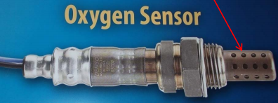
Oxygen Sensor bases have many holes
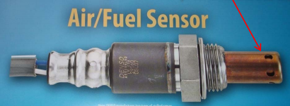
Air/Fuel Sensor bases have fewer holes
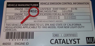
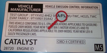
Here’s where you find the sensor type on the Vehicle:
This label shows HO2S (or O2S)
This label shows A/FS*
Sensor Location
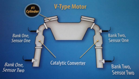
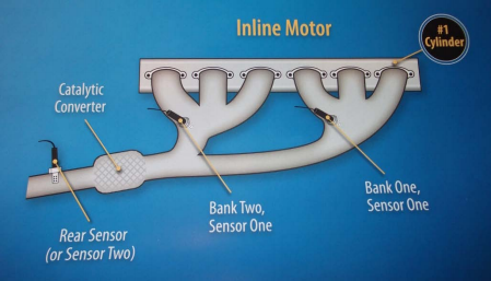
#1 Cylinder is the key to locating the Oxygen Sensor
To locate bank one / sensor one, the key is to identify the # 1 engine cylinder.
In a V-type motor, sensor one (s) are in the exhaust system before the catalytic converter.
In an inline motor, the rear sensor (or sensor two) is in the exhaust system after the catalytic converter
O2 Sensor
Check the voltage signal
Using a 10-megaohm digital voltmeter Hook up the voltmeter’s red probe to the sensor’s signal wire and the black probe to engine ground. (use back probe method, DO NOT pierce the wire)
- Start the engine and let it idle for about two minutes while watching the digital reading on the voltmeter.
- It should be fixed for a short period at around 0.1 or 0.2 volts.
- After two or three minutes, the voltage reading will begin to fluctuate between 0.1 and 0.9 volts.
- If the sensor takes four minutes or more to begin fluctuating, replace it.
- Record the lowest and highest voltage reading from the voltmeter in any one-minute period.
- The voltage should fluctuate constantly between 0.1 and 0.9 volts.
- Replace the oxygen sensor if the voltage:
- Goes above this range,
- Remains below 0.5 volts
- Stays fixed at a particular voltage
- Open and close the engine throttle with a quick motion.
- The sensor’s output voltage should go up and down accordingly
Data Interpretation
O2 Sensor voltage
The O2 sensor normally alternates between 0 V and 1 V. When the value is fixed (stuck) at either 1 V or 0 V, investigate the cause of richness or leanness.
Fixed at 1V | Fixed at 0V |
|---|---|
Inspect weather something is causing a rich air-fuel ratio (see list below) If there are no abnormalities found replace the O2 sensor | Inspect weather something is causing a lean air-fuel ratio (see list below) If there are no abnormalities found replace the O2 sensor |
Possible causes of a Rich Condition
Possible causes of a Lean Condition
Plugged air filter
Faulty air mass meter
Faulty idle control valve
Faulty fuel injectors
Fouled spark plugs
Ignition timing
Faulty air fuel sensor
Associated wiring
Faulty ECU
Faulty MAP sensor
Faulty fuel pressure regulator
Restricted fuel return line
Faulty ignition wires
Faulty oxygen sensor
Faulty EVAP
Engine coolant temperature
Possible causes of a Lean Condition
Vacuum leak
Faulty air mass meter
Faulty MAP sensor
Faulty fuel pressure regulator
Restricted fuel filter
Faulty PCV
Exhaust gas leak
Faulty air fuel sensor
EGR valve
Faulty ECU
Faulty air flow meter
Faulty idle control valve
Faulty fuel pump
Faulty fuel injectors
Associated wiring
Faulty oxygen sensor
Ignition timing
